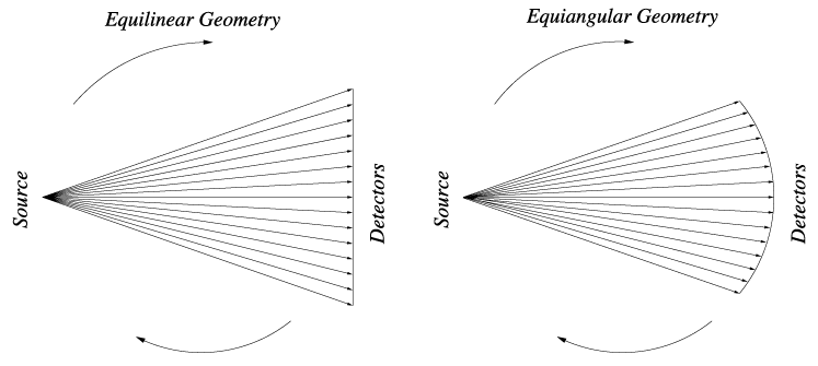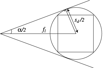

Fan Beam Angle
For these divergent beam geometries, the fan beam angle
needs to be calculated. For real-world CT scanners, this is fixed
at the time of manufacture. CTSim, however, calculates the
fan beam angle, alpha, from the scan diameter and
the focal length as

Empiric testing with CTSim shows that for very large fan beam angles, greater than approximately 120 degrees, there are significant artifacts. The primary way to manage the fan beam angle is by varying the focal length since the scan diameter is usually fixed at the size of the phantom.
To illustrate, the scan diameter can be defined as
Further, the focal length can be defined as
Substituting these equations into the above
equation, We have,
Since in normal scanning s_r = 1, alpha depends only upon the focal length ratio in normal scanning.
Detector Array Size
In general, you do not need to be concerned with the detector
array size -- it is automatically calculated by CTSim. For the
particularly interested, this section explains how the detector
array size is calculated.
For parallel geometry, the detector length is simply the scan diameter.
For divergent beam geometries, the size of the detector array also depends upon the focal length: increasing the focal length decreases the size of the detector array.
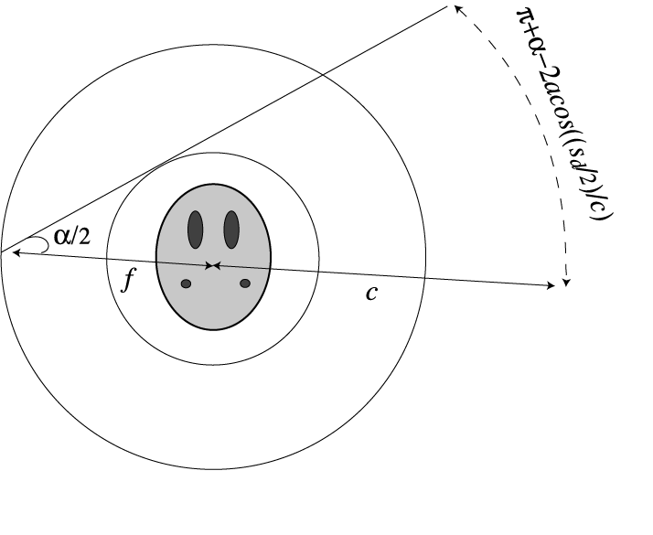
For equiangular geometry, the detectors are equally spaced around a arc
covering an angular distance of alpha as viewed from the source. When
viewed from the center of the scanning, the angular distance is
pi + alpha - 2 x acos ((Sd / 2) / C))
The dotted circle
indicates the positions of the detectors in this case.

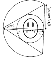
For equilinear geometry, the detectors are equally spaced along a straight
line. The detector length depends upon
alpha and the focal
length. This length,
Dl, is calculated as
